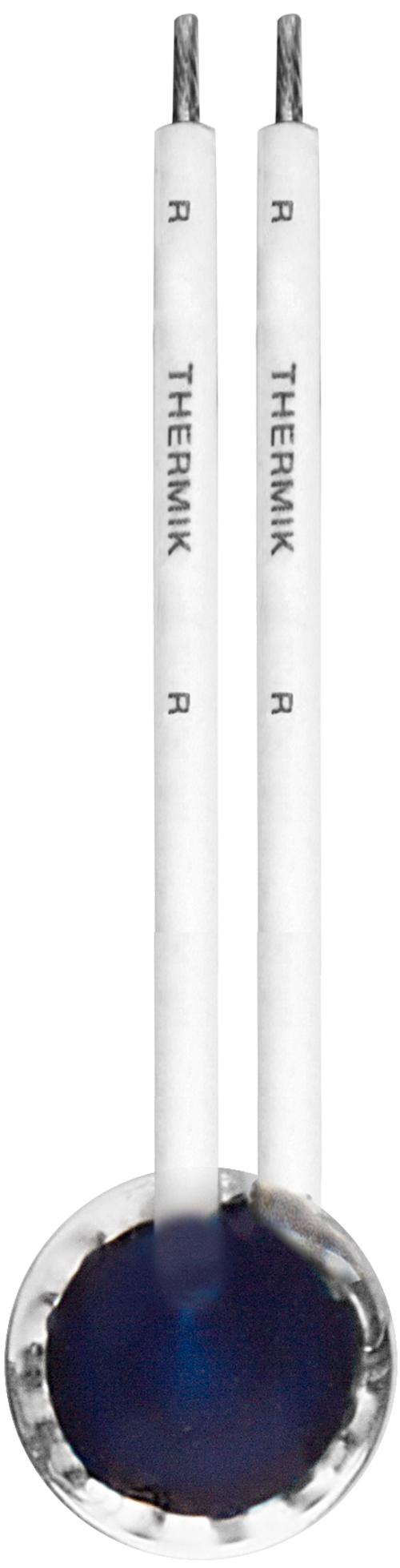
Thermal Protector CF1
Power class:
1,6 A to 7,5 A
Type series:
F1
- normally closed
- resets automatically
- with connector cables
- without insulation

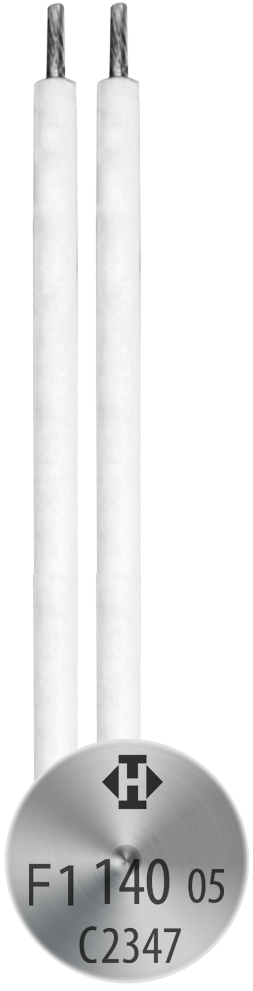
Power class:
1,6 A to 7,5 A
Type series:
F1
The switch mechanism of Type F1 is comprised of five primary parts: 1) a conductive housing, 2) a steel contact cover with stationary contact, 3) a snap-action spring disc, 4) a movable contact, and 5) a bimetallic disc. The conductive housing and steel contact cover form the enclosure, to lock the self-aligning switch mechanism in place. The cover is insulated from the housing, and closes it to appear like a button cell. The snap-action spring disc is the current transfer element and bears the movable contact. It conducts the current flow and self-heating from the bimetallic disc by exercising consistent, steady contact pressure. The bimetallic disc floats within the thermal protector and the movable contact extends through the center of the bimetallic disc without being welded or riveted. When the rated switching temperature is reached, the bimetallic disc snaps into its inverted position and pushes the spring disc downwards. The contact is abruptly opened and the temperature rise of the device being protected is disrupted. If the ambient temperature then falls, the bimetallic disc snaps back into its original position, and the contact is once again closed. The thermal protector may be covered with insulation, mounted into another housing, or left uninsulated. See specifications and ranges described below.