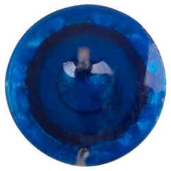
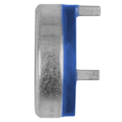
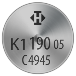
Thermal Protector CK1 Pin
Power class:
1,6 A to 7,5 A
Type series:
K1
- normally closed
- resets automatically
- with pins
- without insulation


Power class:
1,6 A to 7,5 A
Type series:
K1


The switchgear of type series K1 is fixed in a positive lock and is self-aligning between the floor of a conductive housing (1) and a contact cap which is made of steel (2) and insulated from it, plus an integrated stationary silver contact (6) which closes the housing like a button cell. At the same time, the spring snap-in disc (3) which forms the current transfer element bears the movable contact (4) and discharges the flow of current and self-heating from the bimetallic disc (5) by exercising consistent, steady contact pressure. The bimetallic disc (5) is held on the one movable contact (4) which sticks out through this without having to be welded or fixed. As such, it can continually work (exposed) and only reacts to the ambient temperature in the device to be protected. In addition, between the bimetallic disc (5) and and the spring snap-in disc (3) there is an insert made of insulating material (7) in order, for the function itself, to stop insignificant vibration noises as a result of the oscillating bimetallic disc (5) on the spring snap-in disc (3) in applications with uncontrolled, magnetic effects. When the rated switching temperature is reached, the bimetallic disc (5) snaps into its inverted position and pushes the spring snap-in disc (3) downwards. The contact is abruptly opened and the temperature rise of the device to be protected is disrupted. If the ambient temperature now falls, the bimetallic disc (5) snaps back into its start position when reaching the defined reset temperature and the contact is closed again.